Milestone 2
This page demonstrates the core capabilities of the Just the Docs theme, including navigation, mathematical typesetting, and technical diagrams.
Table of Contents
- Milestone 2
- Table of Contents
- 1. Kinematics:\subsection{Robot Kinematics}
- 2. System Achitecture:
- 3. Experimental Analysis & Validation
- 4. Project Management
1. Kinematics:\subsection{Robot Kinematics}
The PacManBot is modeled as a differential-drive mobile robot with state
\[\mathbf{x} = \begin{bmatrix} x \\ y \\ \theta \end{bmatrix}\]where $x$ and $y$ denote the robot position in the global frame, and $\theta$ is the robot heading angle. Since the TurtleBot 4 uses an iRobot Create 3 base, the robot follows differential-drive kinematics. Let $v_L$ and $v_R$ denote the left and right wheel linear velocities, respectively, $r$ the wheel radius, and $L$ the distance between the wheels.
The body-frame linear and angular velocities are
\[v = \frac{v_R + v_L}{2}\] \[\omega = \frac{v_R - v_L}{L}\]If wheel angular velocities ($\dot{\phi}_L$) and ($\dot{\phi}_R$) are used instead of linear wheel velocities, then
\[v_L = r\dot{\phi}_L, \quad v_R = r\dot{\phi}_R\]and therefore
\[v = \frac{r}{2}\left(\dot{\phi}_R + \dot{\phi}_L\right)\] \[\omega = \frac{r}{L}\left(\dot{\phi}_R - \dot{\phi}_L\right)\]The continuous-time kinematic model mapping control inputs to state rates is
\[\dot{x} = v \cos\theta\] \[\dot{y} = v \sin\theta\] \[\dot{\theta} = \omega\]For discrete-time implementation with timestep ($\Delta t$), the state update is
\[x_{k+1} = x_k + v_k \cos(\theta_k)\Delta t\] \[y_{k+1} = y_k + v_k \sin(\theta_k)\Delta t\] \[\theta_{k+1} = \theta_k + \omega_k \Delta t\]Thus, the robot controller converts the wheel motions (or equivalently the commanded linear and angular velocity inputs) into updates of the robot pose $(x,y,\theta)$. This model is used for navigation, trajectory tracking, and pose propagation in the PacManBot system.
2. System Achitecture:
2.2 Module Descriptions
Nodes are grouped by function.
Custom Project Nodes
| Node | Description |
|---|---|
| /audio_node | Handles all robot audio output by selecting and publishing MIDI note sequences based on game events. |
| /game_event_mapper | Central logic translator that converts high-level game events into coordinated actions across subsystems. |
| /game_light_node | Controls LED behavior on the robot to visually represent game state changes. |
| /pellet_manager | Maintains pellet positions, detects collection events, and updates the game state accordingly. |
| /planner_stub | Determines navigation goals based on pellet positions and communicates with Nav2. |
Localization / Mapping / Navigation
| Node | Description |
|---|---|
| /robot_15/amcl | Estimates robot pose using particle filtering with LiDAR and odometry. |
| /robot_15/behavior_server | Executes recovery actions when navigation fails or requires adjustment. |
| /robot_15/bt_navigator | Orchestrates navigation using a behavior tree architecture. |
| /robot_15/controller_server | Converts planned paths into real-time velocity commands. |
| /robot_15/planner_server | Computes global navigation paths. |
| /robot_15/global_costmap/global_costmap | Maintains a global obstacle map. |
| /robot_15/local_costmap/local_costmap | Maintains a local obstacle map for real-time navigation. |
| /robot_15/smoother_server | Smooths navigation paths. |
| /robot_15/velocity_smoother | Ensures smooth velocity transitions. |
| /robot_15/waypoint_follower | Executes sequences of navigation goals. |
| /robot_15/map_server | Publishes the static map used for localization. |
| /robot_15/lifecycle_manager_localization | Manages lifecycle of localization components. |
| /robot_15/lifecycle_manager_navigation | Manages lifecycle of navigation components. |
| /robot_15/collision_monitor | Enforces safety constraints based on sensor input. |
| /robot_15/docking_server | Handles docking operations. |
| /robot_15/route_server | Supports route-based planning strategies. |
Sensor / Perception / Input
| Node | Description |
|---|---|
| /robot_15/oakd | Provides RGB and depth data for perception. |
| /robot_15/oakd_container | Runs OAK-D nodes in a composable architecture. |
| /robot_15/rplidar_composition | Provides LiDAR scan data. |
| /robot_15/joy_linux_node | Captures joystick input. |
| /robot_15/teleop_twist_joy_node | Converts joystick input into robot motion commands. |
Visualization / GUI
| Node | Description |
|---|---|
| /robot_15/rviz2 | Visualizes robot state, map, costmaps, and navigation behavior. |
Library Node Parameter Tuning
No direct parameter tuning was performed on individual nodes within the TurtleBot’s core navigation stack (Nav2), as these were utilized as imported library components. However, all nodes were consistently namespaced through launch file parameters to ensure proper isolation, avoid topic conflicts, and maintain compatibility within the multi-node system architecture.
The primary tuning effort was applied through the Nav2 configuration YAML file, which indirectly affects multiple internal nodes, particularly the global and local costmap layers. The most significant modification was reducing the inflation radius to 0.3 meters.
This change was motivated by observed behavior during testing. With the default inflation settings, LiDAR noise caused frequent fluctuations in the costmap, especially in narrow corridors. These fluctuations resulted in unstable obstacle boundaries, triggering repeated path replanning and occasional navigation failures.
By reducing the inflation radius, the costmap became more stable, allowing the robot to better utilize available free space and navigate more smoothly through tight environments.
Additionally, RViz2 was namespaced consistently with the rest of the system. Custom visualization markers were introduced for pellet positions, enabling clear, real-time visualization of game elements within the navigation map. This significantly improved debugging and system observability during testing.
2.3 Custom Node Deep Dive
This section provides a detailed breakdown of each custom node developed for the PacManBot system. Each node is linked to its source implementation for reference.
/audio_node
Source: audio_node.py
This node acts as the game’s sound dispatcher for the Create3 by subscribing to /robot_15/game_sound and translating incoming string-based sound requests into robot-playable note sequences.
When a message arrives, the callback validates the requested sound against the shared SONGS dictionary and ensures no other sound is currently playing using a busy flag. Valid requests are converted from MIDI notes into frequencies using midi_to_freq(), packaged into an AudioNoteVector, and sent as an AudioNoteSequence action goal to /robot_15/audio_note_sequence.
The node asynchronously handles goal acceptance and completion, clearing its busy state when playback finishes. This design allows other nodes to simply publish a string command while this node manages all low-level audio execution.
/game_light_node
Source: game_light_node.py
This node functions as the lighting controller by subscribing to /robot_15/game_light and translating string commands into LED patterns published on /robot_15/cmd_lightring.
Its logic is organized around a dispatcher that maps commands to either static colors or animations such as startup, game over, power pellet, or ghost capture. Animations are implemented as frame sequences driven by a timer callback, which publishes LED frames one at a time.
Non-animated commands immediately override active animations and publish a solid color. This abstraction allows expressive visual feedback through simple commands.
/game_event_mapper
Source: game_event_mapper.py
This node serves as the central event-to-behavior translator by subscribing to /robot_15/game_event and coordinating light, sound, and motion outputs.
Simple events trigger direct mappings, while complex events (such as death or theatrical start) invoke helper routines that combine multiple behaviors. For example:
- Death: triggers sound, lights, and a timed shake motion using
/cmd_vel - Start theatrical: triggers music, looping lights, and spin behavior
The node uses internal state flags and timers to manage asynchronous behaviors without blocking execution. It effectively acts as the orchestration layer of the system.
/pellet_manager
Source: pellet_manager.py
This node manages pellet placement and persistence within the map. At startup, it loads the occupancy grid map and samples valid pellet locations based on spacing and wall-clearance constraints.
Pellets are stored as a persistent world model and published as RViz markers on /robot_15/pellet_markers.
During runtime, the node listens for removal requests on /robot_15/remove_pellet, deletes pellets by ID, and republishes the updated set. Visualization is refreshed using a DELETEALL marker to ensure consistency in RViz.
/planner_stub
Source: planner_stub.py
This node acts as a simple autonomous planner by selecting the nearest pellet and sending navigation goals to Nav2.
It subscribes to:
/robot_15/amcl_pose(robot position)/robot_15/pellet_markers(pellet locations)
On a timer, it computes distances to all pellets, selects the closest one, and sends a NavigateToPose goal. It then monitors the action lifecycle, handling feedback and results asynchronously.
Upon completion:
- Success: triggers a pellet sound event
- Failure: removes the pellet to avoid repeated attempts
This node implements a greedy planning strategy while delegating motion execution to Nav2.
2.4 Module Declaration Table
| Module / Node | Functional Domain | Software Type | Description | Status |
|---|---|---|---|---|
| LiDAR / Depth Camera | Perception | Library | Acquires raw LiDAR and RGB-D data from TurtleBot 4 sensors. | Completed |
| SLAM Toolbox | Estimation | Library | Builds and maintains an occupancy grid map using LiDAR data. | Completed |
| Robot Localization | Estimation | Library | Fuses odometry and IMU data using an EKF for improved pose estimation. | Completed |
| Diff-Drive Controller | Motion Control / Actuation | Library | Executes velocity commands for robot movement. | Completed |
| Sound and Light Effects | Game State | Custom | Handles synchronized audio and LED feedback based on game events. | Completed |
| Ghost Path Behavior | Game State | Custom | Determines ghost movement logic based on robot position and environment. | Pending |
| Risk-Reward Robot Path Planning | Planning | Custom | Plans robot movement using a tradeoff between pellet rewards and ghost risks. | Pending |
Notable Changes
- Maze Generation Removed: The original maze generation module was removed. Instead, the system now uses SLAM-generated maps directly, simplifying the pipeline and improving reliability.
- Localization Integration: The robot is localized on the SLAM-generated map, which serves as the foundation for pellet placement and navigation.
- Audio & Visual Feedback Added: Light and sound effects were introduced based on instructor feedback to enhance system observability and user experience.
Overall System Status
The system has reached a functional baseline and is ready for advanced game logic development. Currently, the system is capable of:
- Generating a map using SLAM Toolbox
- Localizing the robot using AMCL
- Generating pellets as navigation waypoints
- Navigating to pellets using Nav2
- Removing pellets upon collection
- Triggering synchronized sound and lighting effects
Future work will focus on implementing ghost behaviors and risk-aware planning strategies.
3. Experimental Analysis & Validation
3.1 Noise & Uncertainty Analysis:
Experimental Setup:
Localization performance was evaluated on the Turtlebot4 using Nav2 with maps generated from slam_toolbox. Robot pose estimation was provided by Adaptive Monte Carlo Localization (AMCL). To evaluate the localization uncertainty, the Turtlebot4 was tested in a real indoor environment.
A map of the testing environment was first generated using slam_toolbox, and this map was used by the navigation stack for localization and path planning. The robot pose estimation used during navigation was obtained from Adaptive Monte Carlo Localization (AMCL). This works by fusing LiDAR data with odometry to estimate the robot’s position in the map frame.
The experiments to characterize localization:
- Repeated Initialization Test (Pose Estimation Uncertainty)
- Repeated Navigation Trial (Motion-Based Uncertainty)
Test 1: Repeated Initialization (Stationary Test)
Methodology:
- Robot placed in a position in the generated map
- AMCL was reinitialized multiple times using Nav2 initial pose tool
- Log /amcl_pose into a csv file for later processing
- Repeat initialization 20 times producing 11 different AMCL estimates
Test 1: AMCL Pose Initialization Results
| Samples | Mean X (m) | Mean Y (m) | Std Dev X (m) | Std Dev Y (m) | Mean Radial Spread (m) | Max Radial Spread (m) |
|---|---|---|---|---|---|---|
| 11 | -0.2616 | 2.6982 | 0.0350 | 0.0363 | 0.0481 | 0.0735 |
Test 1: Conclusions
The AMCL pose estimate was evaluated by repeatedly initializing the robot at the same physical location using the 2D Pose Estimate tool. A total of 11 samples were collected.
The results show a positional standard deviation of approximately 3.5 cm in both the X and Y directions, with a mean radial spread of 4.8 cm and a maximum deviation of 7.35 cm.
This indicates that AMCL initialization introduces a small but measurable localization uncertainty, even when the robot remains stationary.
Test 2: Repeated Navigation Trial (Motion-Based Uncertainty)
Methodology:
- Robot was placed by hand to a start location
- The robot pose was initialized through Nav2 - AMCL
- The robot goal coordinate was sent through Nav2
- Robot navigated to the goal through nav2
- /amcl_pose was logged and saved into a csv file
- repeated over 4 trials
Test 2: Navigation Trial Results
Update Timing for Adaptive Monte Carlo Localization
Navigation Analysis Metrics
| Trial | Samples | Duration (s) | Mean dt (s) | Std dt (s) | Min dt (s) | Max dt (s) | Mean dp (m) | Std dp (m) | Max dp (m) | Std X (m) | Std Y (m) | Mean Radial (m) | Max Radial (m) | Std Theta (deg) | Mean Abs dTheta (deg) | Max Abs dTheta (deg) | Mean Sigma X (m) | Mean Sigma Y (m) | Mean Sigma Theta (deg) |
|---|---|---|---|---|---|---|---|---|---|---|---|---|---|---|---|---|---|---|---|
| amcl_t1.csv | 10 | 11.650 | 1.294 | 0.130 | 0.993 | 1.444 | 0.343 | 0.023 | 0.381 | 0.877 | 0.464 | 0.865 | 1.560 | 5.304 | 3.609 | 11.648 | 0.671 | 0.712 | 26.722 |
| amcl_t2.csv | 12 | 12.932 | 1.176 | 0.068 | 1.097 | 1.305 | 0.310 | 0.019 | 0.340 | 0.881 | 0.593 | 0.923 | 1.709 | 2.255 | 1.940 | 4.364 | 0.412 | 0.474 | 20.800 |
| amcl_t3.csv | 11 | 11.756 | 1.176 | 0.074 | 1.029 | 1.281 | 0.299 | 0.031 | 0.344 | 0.787 | 0.510 | 0.810 | 1.565 | 2.379 | 2.614 | 6.691 | 0.275 | 0.295 | 18.068 |
| amcl_t4.csv | 12 | 12.819 | 1.165 | 0.116 | 1.003 | 1.465 | 0.287 | 0.022 | 0.322 | 0.869 | 0.476 | 0.862 | 1.636 | 1.617 | 1.748 | 6.757 | 0.316 | 0.311 | 18.895 |
- AMCL update intervals are non-uniform, averaging 1.1-1.3 seconds
- Low variance across trials means that for this straight line test the frequency was consistent
- AMCL is event-driven from the odom and scan data
- No large spikes in straight line movement, so there is no localization jumps
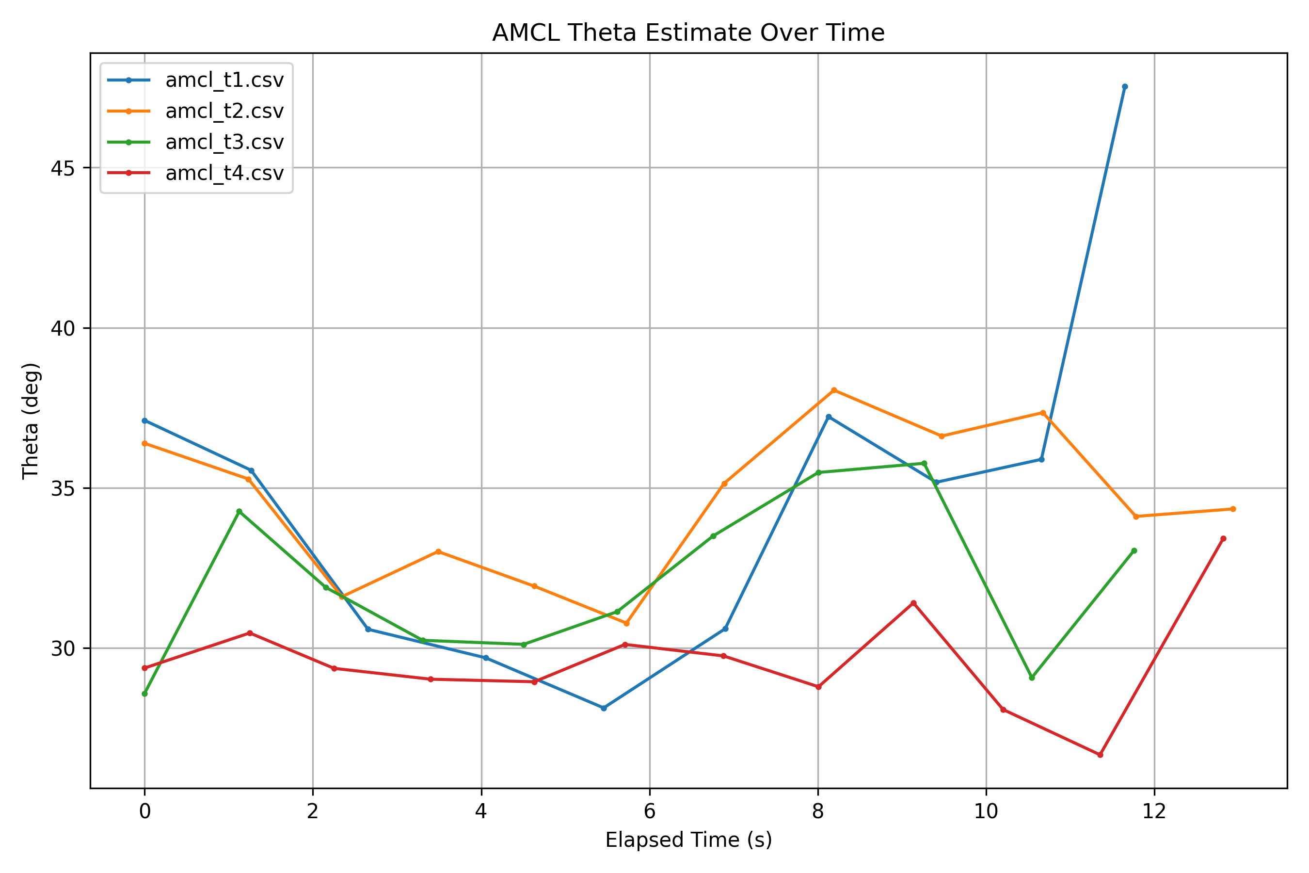
- Oreintation shows higher variability during the straight line test
- Occasional spikes of ~10 degrees
- Heading is more sensitive to sensor noise and scan alignment even in a controlled setting
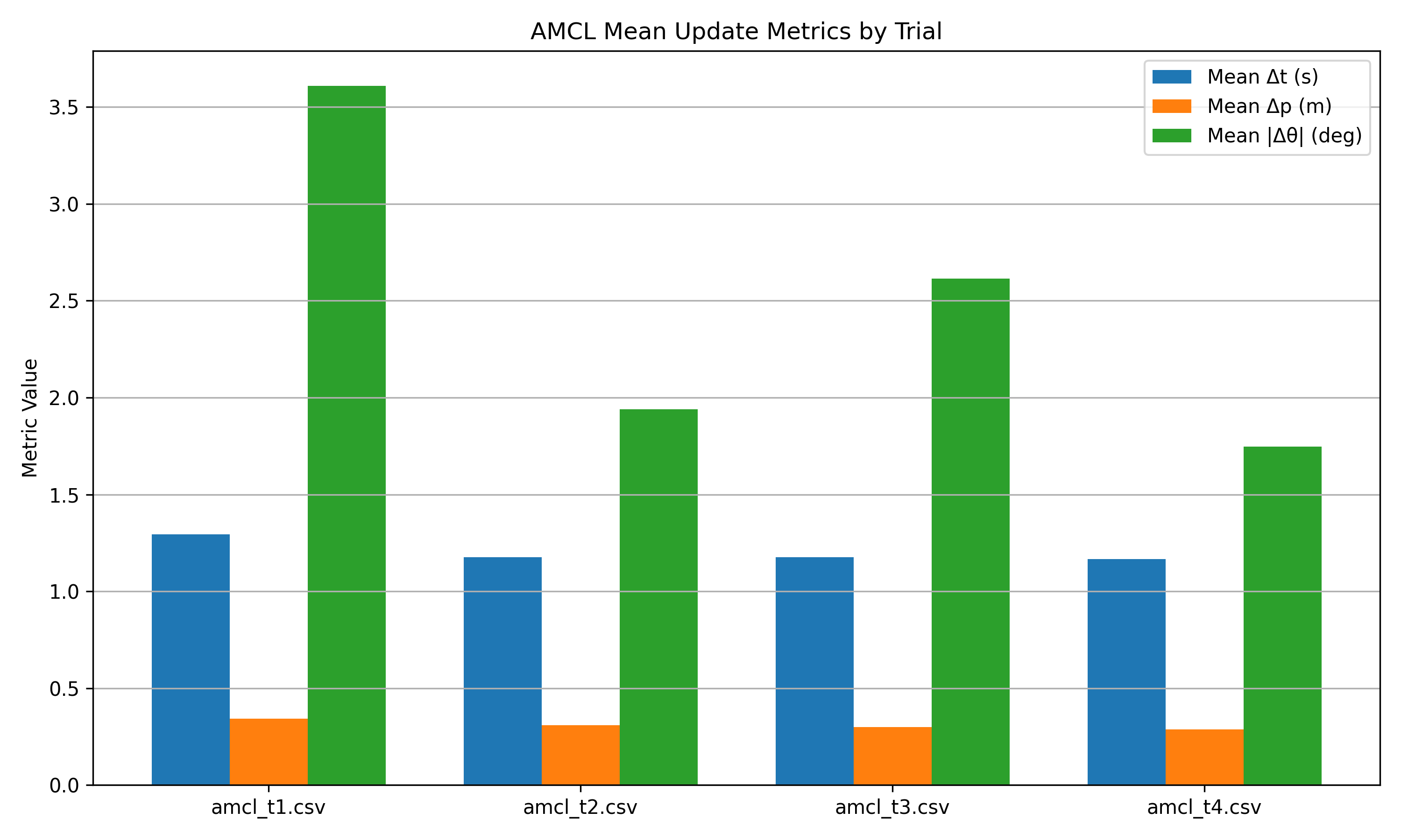
- Mean Δt between samples is roughly the same. So the pose update frequency is looking consistent
- Mean Δposition between samples shows little variation (~0.3m)
-
Mean Δθ varies more significantly between estimates (~1.7-3.6 degrees)
Test 2 Conclusions:
All trials follow similar global motion patterns, since we drove this robot in a straight line in the same part of the house. AMCL is able to provide stable position estimates during navigation, without large jumps between estimates. Pose updates were reliably published during our straight line tests. Orientation exhibits greater sensitivity and correction behavior, due to probabilistic filtering and sensor noise.
3.2 Run-Time Issues:
/amcl_pose was not continuously published while the robot was stationary unless big changes to the scan topic were observed, or if pose was reinitialized with Nav2.
3.3 Milestone Video
The following video demonstrates the Milestone 2 system functionality, including mapping, localization, pellet visualization, and synchronized game feedback.
4. Project Management
4.1 Instructer Feedback Integration
Comments:
Super cool project! Excellent write-up! You are the only team with a Table of Contents. Really well-thought out Safety Protocols.
Fixes:
- Remove the stale “Markdown Features” section at the bottom
Project Idea Feedback:
- I am sure you would need a visual system for debugging, maybe use that for also showing the demo.
- You could add some auditory and visual (LED Ring) feedback when the robot interacts with virtual elements
Questions/Clarifications:
- Have you checked if there are any similar proejects out there in the AR/VR world?
4.2 Individual Contributions:
| Team Member | Primary Technical Role (PTR) | Key Git Commits / PRs | Specific File(s) Authorship (Direct Links) |
|---|---|---|---|
| Sean Vellequette | System Integration, Audio Systems & Analysis Tools | 6aaae2c, d9b96e7 | audio_node.py, pacmanbot_analysis |
| Gabriel Sandys | Autonomous Planning & Game State Systems | 5683d60, 661bb9a, ceb7a7b | pellet_manager.py, planner_stub.py, game_light_node.py |
| Abdirahman Aden | Game Event Logic & Website Integration | 7365ba9, 7c4152f | game_event_mapper.py |